25+ instrumentation amplifier block diagram
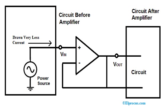
The objective of this experiment is to study some of the special amplification systems used in biomedical signal processing. Here as we can see the transmitted signal is fed to the amplifier as input.

Ad620 Instrumentation Amplifier Pinout Circuit Parameters Faq
The AD620 Instrumentation Amplifier.
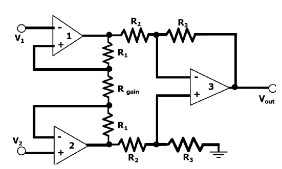
. Shows the basic operation of classic three op-amp based instrumentation amplifier Basic block diagram of instrumentation amplifier is shown in Fig 1. Saving 90 of the passives area and 25 of the FE power. Block diagram of CFIA 11 input stage to reduce the noise and area.
Actually an instrumentation system is used to measure the output signal produced by the transducer and mostly used to control the physical condition producing the output signal. The ECG-Amplifier Project Lab. In addition several dif-ferent categories of instrumentation amplifiers are addressed in this guide.
Together with on-chip low dropout. The op-amp A 3 is the normal difference amplifier forming an. Download scientific diagram Block diagram of the instrumentation amplifier in AE.
The circuitry involved inside the amplifier raises the. A low-cost high-precision instrumentation amplifier option is the AD620 from Analog Devices. The figure below shows the block diagram of an amplifier.
This note provides a detailed theory on how the. The instrumentation amplifier block is common to many CALEX function modules including the model 176 instrument amplifier. There are two main inputs V CM and V.
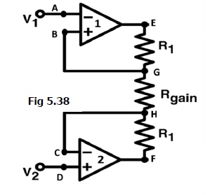
To compensate for the reduction in loop gain due to it the proposed CFIA uses folded cascode OTA FC-OTA in the. Of what an instrumentation amplifier is how it operates and how and where to use it. The op-amps A 1 and A 2 are the noninverting amplifiers forming the input or first stage of the instrumentation amplifier.
This simple DIP-8 component provides low. 1 the first stage of the ECG preamplifier is an instrumentation amplifier with adjustable gain and high. B Input instrumentation amplifier As shown in the block diagram of Fig.

Ad620 Instrument Amplifier Principle Application

Instrumentation Amplifier Circuit Using Op Amp Amplifier Circuit Electronics Circuit
Instrumentation Amplifier Circuit Diagram Advantages And Applications
25 Op Amp Circuits And Projects List

Simple Instrumentation Amplifier Circuit Diagram Using Opamp Equation For Gain Design Working And Construction Also Provide Circuit Diagram Amplifier Diagram

Practical Instrumentation Amplifier Circuit Circuit Diagram Amplifier Electronic Engineering

Lm741 Op07 Lm324 Ad620 Instrumentation Amplifier

Lm741 Op07 Lm324 Ad620 Instrumentation Amplifier
Isolation Amplifier Design Methods Circuit And Its Applications

Instrumentation Amplifier Circuit Design And Applications Circuit Design Amplifier Circuit

Instrumentation Amplifier Circuit Using Op Amp Amplifier Electronics Circuit Electronics Basics

Ad620 Instrumentation Amplifier Pinout Circuit Parameters Faq
Instrumentation Amplifier Circuit Diagram Advantages And Applications

Lm741 Op07 Lm324 Ad620 Instrumentation Amplifier

Instrumentation Amplifier Circuit Using Op Amp Circuit Diagram Electronic Circuit Design Circuit
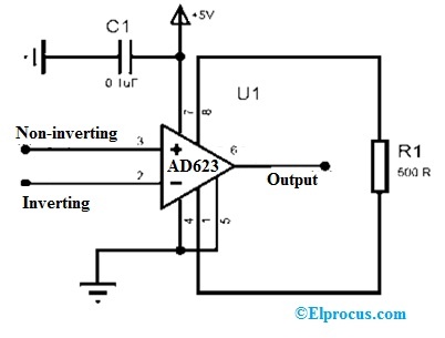
Ad623 Instrumentation Amplifier Datasheet Working Its Applications

Lm741 Op07 Lm324 Ad620 Instrumentation Amplifier